circuits
schematics
diagrams
FreeCircuits.net

Parallel Port Relay Interface
By internum
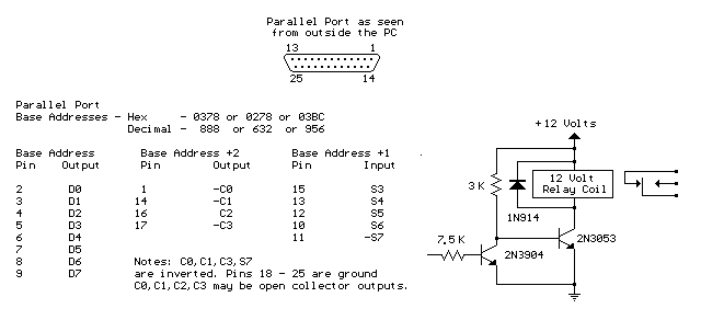
Here is an example of controlling a relay from the PC's parallel printer port (LPT1 or LPT2). The 7.5K resistor is connected to one of the data output lines (D0-D7) and a common connection is made from the negative side of the power supply to one of the port ground pins (18-25). Data is inverted by the 3904 transistor so that writing a "0" to the base address will energize any relays connected to D0-D7 and a "255" will reset them. You may need to try all three base addresses to determine the correct address for the port you are using but LPT1 is usually at Hex 0378. The QBasic "OUT" command can be used to send data to the port. OUT, &H0378,0 sets D0-D7 low and OUT, &H378,255 sets D0-D7 high.

Parallel Port Relay Interface circuit
 1776
1776 ![]() 19 September 2009
19 September 2009
